The settings are located behind the small gear wheel at the top left:

Using Power-Up parameters
As the application always runs in a continuous loop, we recommend working with the power-up parameters of the outputs when programming and not using standard definitions of variables at the start of the application – as it is often the case in many other programming environments.
The following power-up parameters are available:
4 button Keypad module
- Power-Up default brightness value for all LEDs
- Power-Up status for each single LEDs
GPIO module
- Power-Up status for all 4 outputs
Relay module
- Power-Up status for both relay-outputs
- Power-Up status for both universal-outputs
Encoder module
- Power-Up default brightness value for all green LEDs (1…16)
- Power-Up default brightness value for the red LED (16)
- Power-Up status for each single LED
Communication parameters of the RS232 interfaces
The familiar RS232 communication settings can also be found in the module settings:
The communication parameters of the RS232 interface are set here for the first and last bus participant. The PREVIOUS interface of the first module and the NEXT interface of the last module are available for RS232 communication.
If a bus subscriber is a GPIO module, the same communication parameter settings are available for the additional EXTRA interface.
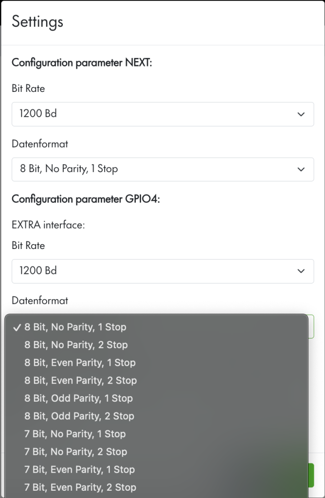
The baud rate and data format can be set:
| Baud rate: | data format: |
|---|---|
| 1200 2400 4800 9600 14400 19200 28800 38400 57600 76800 115200 | 8 Bit, No Parity, 1 Stop 8 Bit, No Parity, 2 Stop 8 Bit, Even Parity, 1 Stop 8 Bit, Even Parity, 2 Stop 8 Bit, Odd Parity, 1 Stop 8 Bit, Odd Parity, 2 Stop 7 Bit, No Parity, 1 Stop 7 Bit, No Parity, 2 Stop 7 Bit, Even Parity, 1 Stop 7 Bit, Even Parity, 2 Stop 7 Bit, Odd Parity, 1 Stop 7 Bit, Odd Parity, 2 Stop |